![]() (1)
(1)
Measurement of Emf Using a Potentiometer
MOTIVATION:
One of the most important instruments used in the electrical laboratory is the potentiometer. The potentiometer is used for measuring voltages, or potential differences, and prior to the advent of the digital voltmeter, was virtually the only instrument capable of measuring very small potential differences. The potentiometer possesses a great advantage over the common voltmeter because, under normal operating conditions, the potentiometer draws no current from the source whose voltage is being measured. Thus it does not disturb the potential difference being measured. Consequently, potentiometers are often used to calibrate other instruments, such as voltmeters and ammeters.
In this laboratory exercise, we will use the concept of the zero current draw of the potentiometer to measure the Emf of a cell. A voltmeter, because it must draw some current, measures only terminal voltage of a cell. The potentiometer, however, is able to measure the true Emf of the cell. In addition to measuring the Emf of the cell, we will measure the internal resistance of the cell.
SPECIFIC OBJECTIVES:
When you have completed the experimental activity, you should be able to: (1) define Emf, terminal voltage, and internal resistance; (2) measure potential differences with a potentiometer; (3) find the internal resistance of a cell from the graph of its terminal voltage versus current; and (4) determine the maximum power that the cell can deliver.
THEORY:
A voltmeter is used to measure the potential difference across some circuit element. Consequently, it is connected so that it provides a path for current through the voltmeter, parallel to the path through the element being measured. This means a slight change in the current in the rest of the circuit occurs because of the introduction of the voltmeter. In most cases there is no objection to this because a good voltmeter is a high resistance instrument and draws such a small current that the effect is negligible.
If one is interested in determining the Emf of a cell, however, the voltmeter measurement will not suffice, since the definition of Emf is the potential difference available when no current is being delivered by the cell. In a new cell the difference between the two cases is very small, but in an old cell the difference may be significant. Old batteries usually have a high internal resistance, and the potential difference seen at the terminals is the Emf minus the potential drop due to the internal resistance (r), or
![]() (1)
(1)
For example, an old dry cell will often register less than 1.3 volts on a voltmeter, with the reading dropping slowly as long as the voltmeter is connected. The same cell will often show an Emf as high as 1.45 volts.

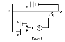
The potentiometer is a device which can measure the potential difference without requiring current to pass through the cell or other device being tested. Thus, it is able to accurately measure the Emf of a cell. In its simplest form it consists of a wire of uniform cross-section, through which a constant current is maintained by the working battery, B (see figure 1). There is a progressive drop of potential along the wire from P to M which is directly proportional to position along the wire.
The cell C to be tested is connected in parallel with a segment of the wire PM, with the positive terminal of the cell at the positive end of the wire. If a galvanometer is connected in series with the test cell, a point Q along the wire PM may be found such that no current passes through the galvanometer. Under these circumstances, the IR drop along the wire from P to Q is exactly equal to the Emf of the cell C.
For a different cell D, a new position Q' may be located such that the IR drop of the segment PQ' equals the Emf of cell D. Again, no current flows through the cell and galvanometer in this condition. Since no current flows through the cell under test, the current in the slidewire is constant and allows us to write
![]() (2)
(2)
If either cell C or cell D has a known value of Emf, then this relationship allows us to determine the remaining, or unknown value. In this way, a known value can be used to "calibrate" the slidewire so that unknown values can be quickly determined.
EXPERIMENTAL ACTIVITY:
The apparatus for this experiment is an improved version of the slidewire potentiometer that permits the user to read quickly and directly the potential difference with a precision of 10-4 volts. The major improvement is that the length of the slidewire is extended by a set of calibrated coils, each coil having a resistance equal to that of the 1-meter slidewire. When properly calibrated, the each coil has a potential drop of 0.1000 volts, and by "counting" how many such coils are in series with the slidewire, the first decimal value of the reading is obtained immediately. The 1.000 meter slidewire also has a potential drop of 0.1000 volts, giving it a linear drop of 0.0001 volt/millimeter. The final three decimal places of the four-place reading are found by reading the contact point on the slidewire in millimeters. The scale of the slidewire is purposely designed to make such a reading easy.
calibration procedure:
Before the potentiometer can be used, it must be calibrated. This is done by using a known Emf to set the potential drop across the coils and slidewire. In this experiment, the known Emf is supplied by a "Standard Cell" or Weston cell, a rather expensive cell the provides a highly reproducible Emf that is constant over long periods of time. In order for the cell to retain the constancy of its Emf, only very tiny currents, of a few microamps, should be drawn from the cell, and only for short periods of time. The standard cell has no function other than for calibration purposes.

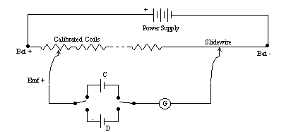
Figure 2
The equipment is assembled according the schematic of figure 2, and approved by the instructor. The value of Emf for the standard cell is read from the tag on the cell, and written down in the data table. The potentiometer is then "set" by selecting the 1.0 coil and moving the slidewire to indicate the reading of the standard cell, and the voltage output of the power supply is adjust to produce a zero deflection of the galvanometer when slidewire key is depressed. Once this adjustment of voltage output is made, it must not be tampered with. This voltage provides the unique potential drop along the slidewire that permits accurate reading of the potentiometer.
You may wish to recheck the calibration periodically during this experiment. That is why the DPDT switch has been included. To check calibration, simply set the Emf value of the standard cell on the potentiometer and change the switch to the standard cell. If no deflection of the galvanometer occurs, then the device is still properly calibrated.
measuring a test cell:
A standard flashlight battery, of nominal 1.5 V value, is used for the test cell, D. This cell is wired as shown in the schematic of figure 2, and the DPDT switch moved to connect it in the circuit in place of the standard cell. The expected Emf value will be around 1.5 volts, so the potentiometer should be initially set using the 1.5 V coil. Briefly depress the contact key, and note the amount and direction of the deflection. You can find the Emf of this cell by adjusting the slidewire until the galvanometer deflection is zero. Read and record the value in your data table.
Replace the test cell D with another cell, similar to it but older. Determine the Emf of this cell, and record it in your data table. Also, measure the voltage of both of these test cells (but NOT the standard cell) with a voltmeter, and record these measurements in your data table as well. When finished testing this old cell, remove it and reconnect test cell D.
measuring internal resistance of a cell:
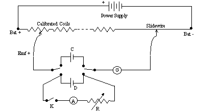
Now we need to be able to draw a current from the test cell while we measure the potential difference between its terminals. To do this, we add the side branch K-A-R as shown in figure 3. The resistor R is a variable resistor that can be adjusted to control the current, which is measured by ammeter A. The switch is used to turn the current flow off, so as to avoid excessive drain on the test cell.

Figure 3
You will need to work quickly to make simultaneous measurements of both current and terminal voltage for this cell. It is suggested that you take about 10 data points, allowing the current to range between values of 0.100 A and 2.0 A. Set the current with the resistor, make the voltage measurement quickly, and then turn off the current until you are ready to make the next measurement.
Since the current sometimes changes during the time a reading is being made, it is important to read both values at the same time, and record them as precisely as possible. Being both quick and precise will help your values to come out correctly.
To analyze this data, plot a graph of terminal voltage (V) versus current (I) for the test cell. Under ideal circumstances this should be a straight line, so you should fit the best possible line to this data. Once this fit is accomplished, the Y-intercept value is the Emf of the cell, the slope of the line is the negative of internal resistance (-r), and the X-intercept is the maximum current that the cell can deliver (Imax). Indicate these values in the data table. Also, compare the value of Emf from the graph with the value you measured for this cell early in the experiment using percent difference.
You should also have sufficient data to determine the maximum power which the cell can deliver to an external load. You may have to extrapolate some data points by using your "line" from the graph to estimate the voltage at high currents, but that is perfectly permissible in this circumstance. To find the power, plot the product of voltage and current (V*I) as a function of current (I). This graph should be a curve, actually a parabola that opens downward. The highest point on the curve is the maximum power, Pmax, that the cell can deliver.
FINAL SUMMARY:
You should report the best values of Emf and internal resistance for the cell that you have just measured, along with your estimates of maximum current and power that it can deliver. Report any conclusions that you have drawn about the Emf and internal resistance of "old" cells, and any other conclusions that you have made as a result of your observations.