
A Simple Electric Motor
MOTIVATION:
One of man's most widely used inventions has been the electric motor. From clocks to blenders, from drills to stereo equipment, the electric motor finds a use for turning electrical energy into mechanical work. The motor is sometimes the main mechanism in a device, and sometimes it is only an auxiliary item needed to complete a function. But wherever we turn, to our cars with power windows and seats, to our offices with computers, Dictaphones and copiers, to our homes with myriad electrified appliances, the electric motor produces action.
This experiment is designed to examine several types of DC and AC motors, so that the fundamental principles of their operation may be observed and understood. We will try to point out the similarities and differences, and even show one type of motor that runs on either DC or AC electricity.
SPECIFIC OBJECTIVES:
When you have completed the experimental activity, you should be able to: (1) identify the armature, brushes, commutator, and field winding of a motor; (2) understand how an electric motor transforms electrical energy into mechanical motion; (3) distinguish between shunt-wound and series-wound motors; and (4) correctly wire the elements of various motors.
Part I: Permanent Magnet DC Motor
THEORY:
The simplest motor is a permanent magnet DC motor. It consists of 3 basic parts, which we call the armature, the field, and the commutator. As you examine the experimental apparatus, you will see a horizontal iron bar, wrapped with a coil of wire, mounted so that it is free to rotate. This is called the armature of the motor, and when current is applied to the armature winding, the armature acts like an electromagnet.
The current is supplied to the armature through the commutator, which is the brass ring on the vertical axle shaft, located above the armature. This brass ring is split into two halves, each of which has one end of the armature winding soldered to it. Current is supplied to the armature by metal or graphite "brushes," which make electrical contact by rubbing or brushing against the brass ring. Because the brass ring is split into two parts, it is referred to as a split-ring commutator.
A magnetic field is required in the vicinity of the armature. The simplest way to do this is to use permanent magnets on either side of the armature. Another very common technique is to wrap a winding around an iron core and use the resulting electromagnet to supply the field. This latter construction is called a field winding. We will examine both types during this experiment.
The motor works like this: When current is supplied to the armature, one end becomes a north pole, and the other end a south pole, magnetically. Since the armature lies in a magnetic field, which we will assume to be due to permanent magnets located nearby, there are magnetic forces acting on the armature, such that the north pole end of the armature is attracted to the south pole of the external field. A similar attractive force will exist between the south pole end of the armature and the north pole of the field. These two forces create a torque that causes the armature to rotate.

The split ring commutator causes the armature current to reverse direction when the armature turns and the brushes contact alternate ring segments, which causes the polarity of the armature to reverse. Thus, as the north pole end of the armature swings by the south pole of the field, it reverses to a south pole itself and is now repelled by the field, and pushed toward the other pole of the field. The continual reversal of the polarity of the armature, whenever it has turned 180o, is what permits the rotation to continue.
EXPERIMENTAL ACTIVITY:
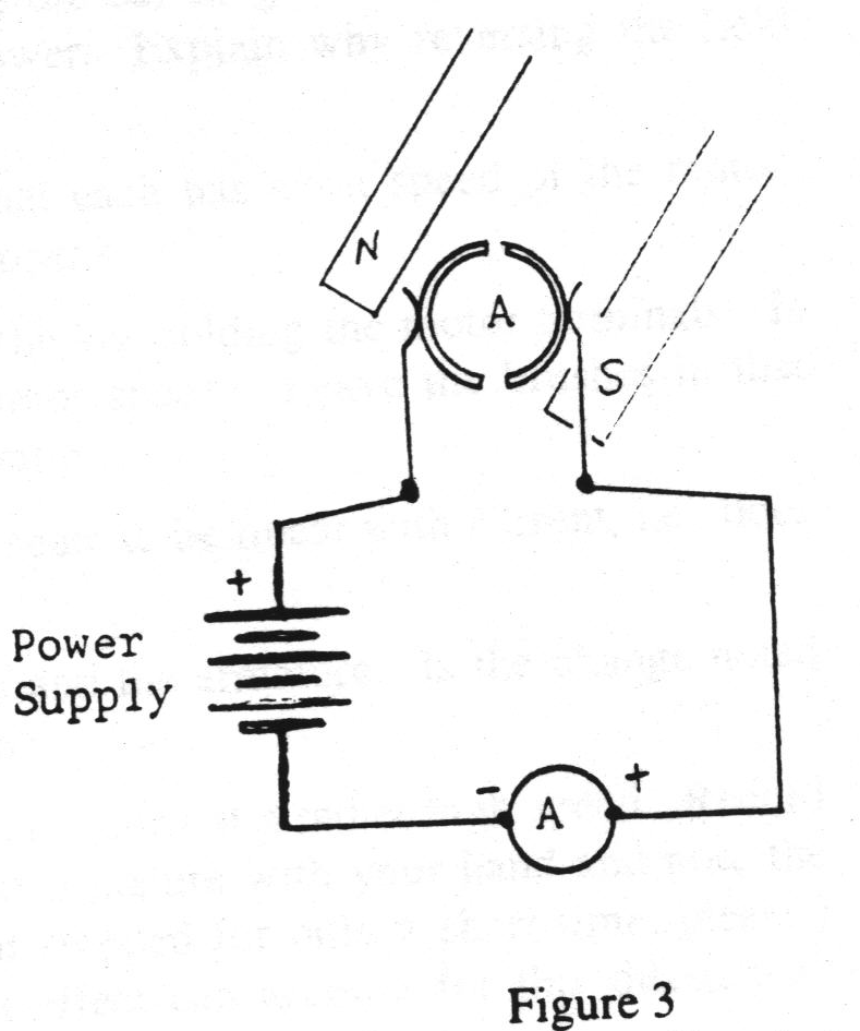
The brushes should lightly touch the split-ring commutator at the top of the St. Louis Motor. Carefully adjust these, if necessary. Remove the electromagnetic field coil, if attached, and remove the permanent magnets. Wire the motor according to the schematic shown in figure 3. Be sure to use the DC output terminals of the power supply. The control knob on the power supply will be used to control the current supplied to the motor. Since the breaker is set for 3 A, you should not exceed this value for more than a few seconds. Be sure your circuit wiring has been approved by the lab instructor before you turn on the power supply.
Start with some basic observations regarding the armature. Observe and record carefully what you observe, and answer the questions.
Set the armature so that it is pointed toward the front of the motor. Turn on the power supply, and increase the power until the current is 0.5 A. Test the polarity of the armature with a compass. Which end of the armature is the N pole? Which end is an S pole?
Rotate the armature 180o and check the polarity again? Which end is the N pole now? Why did the armature change polarity? What conclusion do you draw concerning the purpose of the split-ring commutator?
Interchange the leads at the motor terminals, and repeat the polarity test. Which end of the armature is the N pole now? What will be the effect on motor operation if the direction of current applied to the motor is reversed?
Turn the armature slowly and locate the position where its polarity reverses. What determines this reversal position? How can the position be changed?
Place the bar magnets in the magnet holders, so that the pole ends are about even with the armature axis. Be sure that there is an N pole on one side of the motor, and an S pole on the other. Check to see that the armature can rotate freely without striking the magnets. Think about the polarity tests above, and the direction of the field due to the bar magnets, and predict the direction that the motor will turn. Write down your prediction and defend it logically. Slowly turn up the current until the armature turns on its own (you may have to nudge it to get it started). Is the direction the same as you predicted?
Try various starting positions for the armature. What position seems to work best for starting without a nudge? Why does the motor not start equally well in all positions? What might be done to improve its starting ability?
What direction will the armature rotate if the motor terminal leads are reversed? Write down your prediction, and test to see if you are correct.
Reverse the direction of the magnetic field by removing the bar magnets and reversing them. What effect will this have on the motor? Test your answer. Explain why reversing the field affects the motor's rotation.
Do each of the following tests and observe the effect that each has upon speed of the motor. Record your observations, and explain why each effect happens.
Set the power supply at about 2 or 3 amps, so that the motor turns at a rather high speed. Record the value of current at this high speed, and then stop the armature with your hand and note the current reading when the armature is stopped. (Keep it stopped for only a short time, please.) What difference do you notice in the readings? What effect can account for this difference? What might occur if an electric motor is overloaded?
Observe the way the ammeter reading changes as the armature is released and returns to full speed. Do you note a gradual change of current as the armature speeds up? Why should this occur?
Summarize the major concepts of permanent magnet motors in a paragraph.
Part II: Shunt-Wound and Series-Wound DC Motors
THEORY:
Figure 4 shows the schematic arrangement for shunt-wound and series-wound DC motors. In these motors, the permanent magnets are replaced by an electromagnet, and a single power source provides energy to both the armature winding (A) and the field winding (F). The primary difference in the two types is the connection of the armature winding and the field winding. In the first type, the field winding is connected in parallel with the armature winding, and thus a portion of the current is shunted around the armature through the field winding. This type of motor is called a shunt-wound motor. A primary characteristic of this type of construction is that the field intensity is essentially constant, since the field winding is in parallel with the armature.
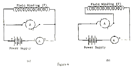
The second type has the field winding in series with the armature winding, so that all current passes through both windings. For obvious reasons, this is called a series-wound motor. This motor tends to have a high starting torque, and tends to achieve a definite maximum speed of rotation.
Many motors are constructed with field coils which are partially shunt-wound and partially series-wound, called compound winding, to achieve some particularly desired intermediate characteristics.
EXPERIMENTAL ACTIVITY:
Remove the bar magnets from the motor, and attach the electromagnet. Be sure the armature is free to rotate without striking the electromagnet. Wire the motor in the shunt wound configuration shown schematically in figure 4a. After the circuit wiring is approved, turn the power supply on to its minimum and slowly increase the power until the motor just begins to turn. Record both the direction of rotation and the value of the starting current.
For the following questions, predict an answer and then test your answer experimentally. If your answer is incorrect, try to figure out why it was.
Rewire the motor in the series-wound configuration of figure 4b. After circuit approval, set the power supply to its minimum, and turn it on. Slowly increase the power and record the direction of rotation and the value of the starting current for this configuration. Is this starting current higher, lower, or the same as the starting current of the shunt-wound motor? Why?
Again, for the following questions, predict the answer and then test it experimentally. Work to understand why the motor functions as it does.
Write a short summary paragraph that compares the two types of field windings in these motors. How are they similar? How are they different?
Part III: Universal (AC-DC) Motor:
THEORY:
You should have noticed that reversing the supply leads to the series-wound motor did not change the direction of rotation of the motor. That is because both the armature polarity and the field polarity changed together. This effect allows the series-wound motor to be used with either DC or AC current, hence the name "Universal Motor."
EXPERIMENTAL ACTIVITY:
Remove the ammeter from the circuit of the series-wound motor, and shift the supply leads to the AC terminals of the power supply. Turn the power supply on, and turn it up slowly until the motor is spinning. What direction does it turn? How can you change the direction of rotation?
Summarize these observations in a brief statement.