EQUILIBRIUM OF FORCES AND TORQUES
RATIONALE:
Much of the subject we call mechanics was summarized by Newton in the Laws of Motion about 1700. The first of these laws states that an object, acted upon by no net external force, will move with constant velocity; if at rest, it will remain at rest, if in motion, it will continue to move in a straight line with constant speed. Such an object is said to be in equilibrium.
The first law can be extended to rotational motion by introducing the idea of torque and the concept of angular acceleration. Thus a body is said to be in complete equilibrium if (1) the vector sum of all external forces acting on the object is zero (no linear acceleration results) and (2) the sum of all external torques acting on the object is zero (no angular acceleration results).
In this experiment you will be asked to verify these two conditions of equilibrium in a special case where the object is at rest. Note, however, that the concept of equilibrium in no way implies the absence of motion - only the absence of a change in the motion.
SPECIFIC OBJECTIVES
:When you have completed this experimental activity, you should be able to: (1) calculate the weight (Newtons) of an object of given mass (kilograms); (2) define equilibrium and state the two conditions which must be satisfied for complete equilibrium; (3) find the sum of two or more vectors; (4) find the component of a vector along an arbitrary direction; (5) define torque and give its units of measure; (6) calculate the torque exerted by a force about an axis; (7) find the sum of a group of coplanar torques; and (8) define colinear, coplanar, and concurrent as the words are used to describe forces.
EXPERIMENTAL ACTIVITY:
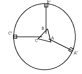
At your work station you will find a board with three strings attached, a sheet of paper, a "force table", and various weights with hangers. Place the paper on the top of the force table, put the board on top of the paper, and spread out the strings so that they make approximately equal angles with each other. Extend them over the edge of the force table, with a weight hanger on each string, and position a pulley under each string.
Next, place weights of differing amounts on each weight hanger, say from 300 to 600 grams. The peg in the center of the force table will keep the board in place until you have achieved equilibrium of the forces. Move the pulleys (and the strings with them) until the board is in equilibrium in the center of the force table. It may be necessary also to adjust the weights on the hangers. Work with it until the board desires to remain in the center, even when nudged a little.

When the board comes to equilibrium, take a straight edge and draw lines on your paper along each of the three strings. Label these lines as AA¢ , BB¢ , and CC¢ as in the figure. These three lines show the lines of action of the three forces acting on the object. Near each of these lines, record the force (in Newtons) exerted on the board. The forces are just the weights of the various masses and are given by W = mg where m is the mass in kilograms and g is the acceleration of gravity.
Now remove the weights and the board, and take the sheet of paper on which you drew the lines AA¢ , BB¢ , and CC¢ . Extend these lines toward the center of the paper until they intersect. If you have been careful, these three lines should intersect in a common point, which you should label O. If they do not intersect at a common point, repeat the previous steps. Carefully measure the angles between the lines, and check to be sure you have indicated the correct force for each of the three lines. From here on, each student should work independently in analyzing the experiment.
ANALYSIS OF DATA:
We often represent a vector quantity (force, velocity, momentum, etc.) as an arrow in a scale drawing. The magnitude of the vector quantity is represented by the length of the arrow (drawn to some convenient scale) and the direction of the vector quantity is given by the direction (or angle) of the arrow.
Choose some convenient scale for your experimental data, something like 1 N = 2 cm, and make an accurate scale drawing of the forces exerted by the three strings. Do not draw any of the three forces along either the x- or y- directions. In this case, the x and y directions are arbitrary and your analysis becomes general in nature. Now find the x- and y- components of each of the three forces, and mark the values on your drawing. Show the sum of the x- components and the sum of the y- components for your data. If either sum is not zero, calculate a relative error to determine an estimate of your accuracy.

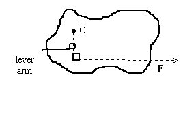
Torque can be loosely defined as a measure of the ability of a force to produce rotation. Operationally, the torque is defined as the product of the force (Newtons) and the lever arm (meters). The lever arm is the perpendicular distance from the rotational axis, O, to the line of action of the force, as in the diagram.
For your report, make a second copy of the scale drawing of the forces acting on the object. On this new drawing, pick an arbitrary point that is well removed from the lines of action of the three forces, and label it as pint O. Extend the lines of action of the three forces until they pass by the point O, and draw the lever arms for the three forces. Measure the lever arms as drawn on the paper, and compute the torque of each of the forces. Now sum the three torques, using the convention that counterclockwise torques are positive and clockwise torques are negative. You may do the analysis on the face of the drawing. Indicate the relative error if the sum of the torques is not identically zero.
FINAL SUMMARY:
Report you relative errors for the x-force, the y-force, and the torques. What do these numbers indicate? Were the two conditions of equilibrium satisfied? What does it mean for an object to be in equilibrium?