![]() (1)
(1)
Capacitors:
The Storage of Electric Charge
MOTIVATION:
The first circuit element introduced in most physics courses is the capacitor, a pair of parallel plates that store equal but opposite charges on them. This simple device, in the forms most often used in actual circuits, is one of the most diversely used circuit elements in all of electronics. It is used to filter noise from sensitive circuits, as a timing element in oscillator circuits, as a tuning element in radio circuits, and for a host of lesser uses.
In this exercise, the capacitor is introduced in terms of its ability to store charge, and analyzed in terms of the relationship between charge and potential difference. The student also examines simple series and parallel combinations of capacitors.
SPECIFIC OBJECTIVES:
When you have completed this laboratory exercise, you should be able to: (1) define charge, current, potential difference, and capacitance, and give proper units for each; (2) understand the relationship between current and charge; (3) conduct an experiment that measures capacitance as a ratio of charge to potential difference; and (4) determine experimentally the resultant capacitance of series and parallel combinations of capacitors.
THEORY:
As discussed in the textbook, a capacitor is a pair of conducting plates separated by a thin insulator. When connected to a source of Emf, positive charge builds up on one plate and negative charge on the other, creating an electric field between the two plates. Because work is required to create the separation of charge and establish the electric field, this device stores energy in the form of electrical potential energy.
The capacitance of a capacitor is defined as the ratio of the charge stored on the plates of the capacitor (Q) to the potential difference between its plates (V). Thus,
![]() (1)
(1)
The difficulty in making this simple determination of capacitance is that while potential difference is easy to measure, charge is somewhat more challenging. One technique of previous years has been the use of a ballistic galvanometer, a rather delicate and expensive device whose deflection is proportional to the amount of charge flowing through it.
The advent of integrated circuits has brought a somewhat simpler and very inexpensive solution to the problem of measuring charge. The key to this is an IC current regulator, which we will refer to as a "charge pump." The charge pump is, in reality, simply a 1 mA constant current source. Since current is the rate at which charge is transferred, or
![]() (2)
(2)
then charge is![]() . For a constant value of i, this becomes simply Q = i t.
. For a constant value of i, this becomes simply Q = i t.
When the charge pump is connected across the terminals of an uncharged capacitor, it will transfer charge from one plate to the other at the steady rate of 1 mC/s, so that the total charge on the plates is
![]() (3)
(3)
Thus, the charge transferred, in millicoulombs, is numerically equal to the time in seconds that the pump is connected to the capacitor (and the switch turned on, of course). A voltmeter connected across the capacitor will show a steady increase of potential difference as the charge pump operates.
The capacitance is easily determined by applying the charge pump to the capacitor of interest and measuring the time required for the potential difference to reach some final value V. Specifically, the expression for capacitance is found from equations (1) and (3) to be:
![]() (4)
(4)
assuming that the capacitor is initially uncharged.
capacitor combinations:
When capacitors are connected in parallel, the charge stored in the combination is divided between the capacitors in such a way that the potential difference across the plates of each capacitor in the parallel combination is the same. Thus
![]() (5)
(5)
Using equation (1), then
![]() (6)
(6)
For capacitors in series, the same charge must be on the plates of each capacitor in the combination, since the same current passes through each one. The total potential difference of the combination, however, is the sum of the individual potential differences across the capacitors in the combination, or
![]() (7)
(7)
Since from equation (1) we find V = Q/C, we can write
![]() (8)
(8)
from which we can factor out the common charge Q to get
![]() (9)
(9)
SAFETY:
Since capacitors store large quantities of charge and are capable of extremely rapid discharge, students should treat the capacitors with great respect. A charged capacitor is capable of giving someone a large electrical shock without warning. Students should be careful not to touch the terminals of a capacitor unless they know it is discharged, and you should always discharge a capacitor when you have finished using it. Capacitors may be discharged by touching the ends of a wire to both terminals simultaneously. In an effort to ensure the safety of students in this lab, only very small potential differences are used.
EXPERIMENTAL ACTIVITY:
Basic equipment is the charge pump, a voltmeter, and two capacitors of different size. The charge pump is set at 1.00 mC/s, and can be considered accurate to three significant figures.
A. single capacitor measurements
Be sure that capacitors are discharged before beginning your measurements.
Connect the positive output terminal of the charge pump to the positive terminal of the large capacitor, and the negative terminals to each other. Use the voltmeter to measure the potential difference across the capacitor by touching the voltmeter leads to the capacitor terminals. Charge the capacitor by depressing the switch button on the charge pump, and measure the voltage as the capacitor charges. Record time (t), charge (Q), and voltage (V) every twenty seconds until the potential difference across the capacitor reaches 3 volts.
Plot V vs. Q for this data, and note the shape of the curve. If the graph is approximately linear, find the slope of the line. Watch the units carefully. The capacitance should be the reciprocal of the slope. Record this value of capacitance in your data table.
Repeat this procedure for the smaller capacitor, making measurements every 10 seconds until the potential difference is 3 volts. Record this data in a second data table, and plot the data on the same graph as the first. Be sure to distinguish the two and label them carefully. How is this graph different from the first? What is the value of this capacitor?

Be sure the capacitors are discharged before beginning your measurements.
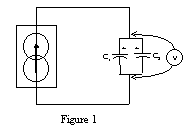
Connect the positive terminals of the two capacitors together, and connect them to the positive terminal of the charge pump. Connect the negative terminals of the two capacitors together, and then connect this side of the combination to the negative terminal of the charge pump. Use the voltmeter to measure the potential difference across the capacitors. See figure 1.
Charge the parallel combination to a voltage of 1.00 volts, carefully measuring the time to reach this potential difference. What is the capacitance of this combination? Does this parallel combination have more or less capacitance than the individual capacitors? What is the addition rule for parallel capacitors? Compare the equivalent capacitance you have just measured to the expected equivalent capacitance based on your measurements in part A, using percent difference.
Can you determine which capacitor has more charge? Discharge each of the two charged capacitors through the charge pump, one at a time, to measure how much charge it has. Connect the negative terminal of the capacitor to the positive terminal of the charge pump, and positive to negative. Then the discharge rate is 1 mC/s. Determine the time to discharge each capacitor to a potential difference of zero. What is the charge on each capacitor?

Be sure both capacitors are discharged before you begin your measurements.
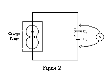
Connect the two capacitors in series, and connect the combination to the charge pump. Charge the series combination to a voltage of 1.00 volts, carefully measuring the time to reach this potential difference. What is the capacitance of this combination? Does this series combination have more or less capacitance than the individual capacitors? What is the addition rule for series capacitors? Compare the equivalent capacitance you have just measured to the expected equivalent capacitance based on your measurements in part A, using percent difference.
Check the amount of charge each capacitor has by discharging them individually through the charge pump? Do they have the same charge? What can you conclude about the charge on capacitors in series?
FINAL SUMMARY:
You should indicate your experimental values for the two capacitors, and for the series combination and the parallel combination. Your conclusions should indicate something about the addition rules for combinations, and about the relationship of charge and potential difference for capacitors, as well as any conclusions you were able to draw from observations during the experiment.